Output Devices
This week we have to add an output device to our board and program it. I decided to work with the 2X16 LCD screen because I want to use that in the SmartWatch of my final project. I also wanted to try with the Fabduino as well.

For the Fabduino I began with Edward Baafi's Fabduino Board Version 2 on his How to Make site. I milled two board. For the first one I soldered the ATmega 168 in the wrong orientation and when I was desoldering, some traces were peeled off. I then worked on the second board and the stuffing was successful. However, I was not able to burn the bootloader to the board using Arduino IDE. I did the checking using multimeter and tried every possible configuration of the jumpers to the ISP and still no success.
I decided to try with Edward's another board known as the FabKit I/O V.2.
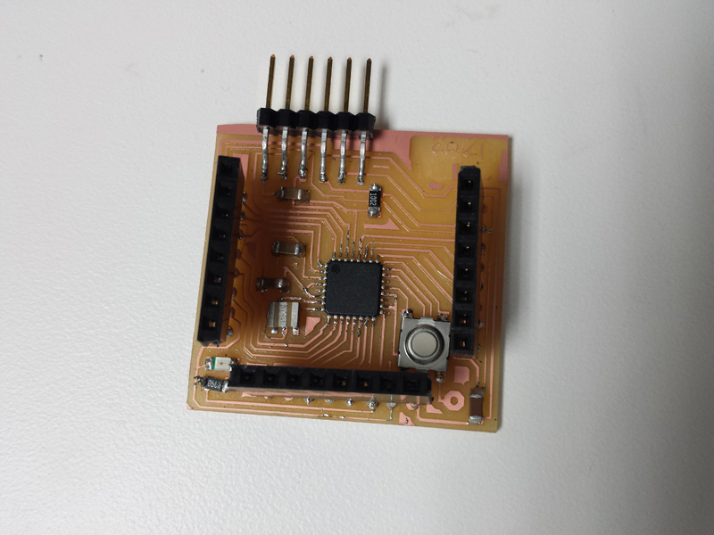
Everything went smoothly except for the burn Bootloader part. It took me a while to figure out the correct configurations for the ISP. Below are two diagrams that I found useful.


During the Bootloader burning process I was using a jumper wire to connect the RST on the board and that of the ISP head. However, there were always errors. I used a multimeter to check the trace between the RST pin of the Atmega 168 chip and the RST pin on the lower right of the board and it was ok. Anyway, I tried to use the jumper wire to directly touch the RST pin of the chip and it worked! That was really weird.
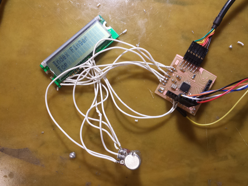
I tested the board with the Blink example and it worked fine. I then started to work on the LCD. Soldering the wires to the LCD really took me some time. Basically I was looking at the below 2 diagrams while figuring out the correct pins to connect. I also added a 10K Potentiometer to adjust the contrast of the screen.

After that by using the LiquidCrystal HelloWorld example of Arduino IDE, I managed to get the LCD working.
The next step would be referencing the Fabduino schematic and creating a new board for my smart watch.